
In a single phase transformer, there is a primary winding and a secondary winding. The winding to which AC voltage source is connected is known as Primary winding, and the winding to which Load is connected is known as Secondary winding. Then what is different in a no load transformer ?
If there is no load connected with the secondary winding then, it is called as a no-load transformer. We will discuss no load transformer with its phasor diagram in this post.
In a no load transformer, the secondary side is open circuited. Hence, there will be no current flowing in the secondary circuit.
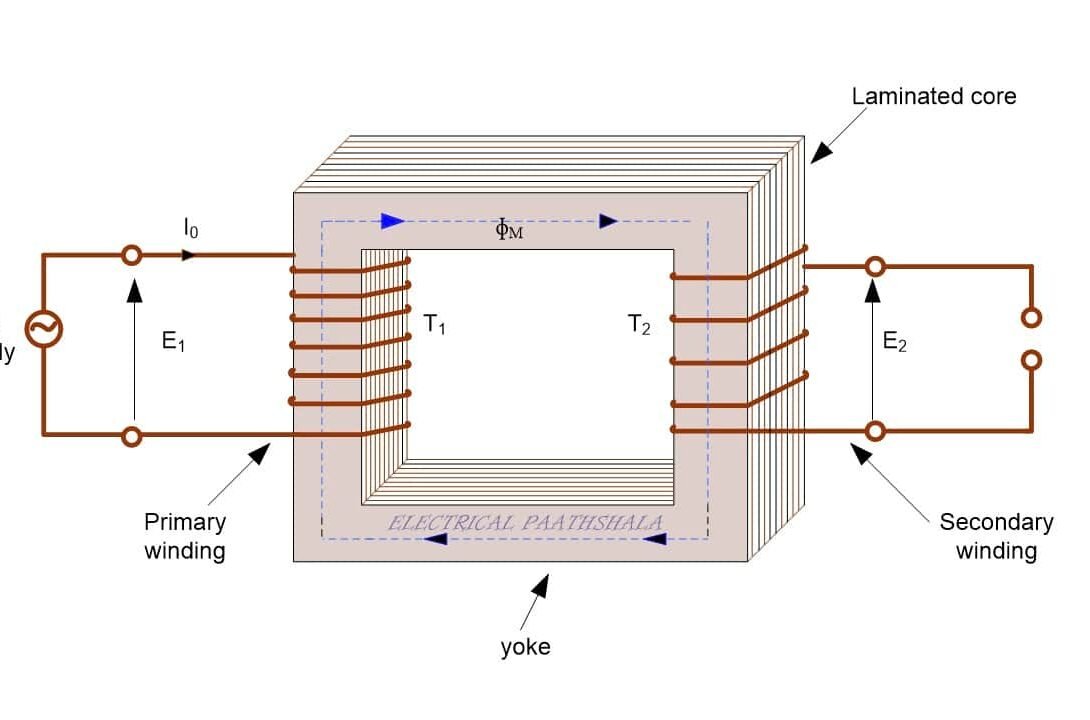
A small current will flow in the primary side, which is known as the no load current and it is denoted as “Io”. This no-load current Io has two components, magnetizing component (Iµ) and working component (Iw).
Magnetizing component (Iµ) :
This component is known as magnetizing component, because it is actually use to magnetize the core of the transformer. We can also say that, Iµ is used to set up flux(ɸM) in the core. Now, as the flux ɸM is developed by the Iµ, so they both will be in phase to each other as shown in the phasor diagram below.
This current Iµ is also called reactive or wattless component of no-load current, because this component does not consume active power. It is not responsible for any losses in the circuit.
Working component (IW) :
This current IW is basically responsible for the losses in the transformer. Mainly, it is responsible for the hysteresis and eddy current losses but it is also responsible for the negligible I2R losses.
Note:- I2R losses are take place due to winding resistances, hence, they are negligible in No-load condition.
As we know that this component is responsible for the losses in the transformer, and it actually does some work in the transformer, hence it is called working component or active component or wattful component of no-load current.
IW is in phase with the applied voltage V1.
Note:-The no-load current Io is small of the order of 3 to 5 percent of rated current of the Primary.
Phasor diagram of transformer on no-load
We will draw the phasor diagram of transformer under no load condition in few steps, then by combining all the steps together, we will draw a final figure. This method will be very easy to understand, let’s start.
Step 1
Take flux ɸM as the reference phasor, as shown in the figure below.
Step 2
Emf equation of no load transformer is given by,
\(\phi ={ \phi }_{ m }\sin { \omega t } \)
To read about emf equation of a single phase transformer, click here
Since, the emf E1 and E2 are induced by the same flux ɸM, so they both will be in phase to eachother.
But, E2 will differ in magnitude from E1 because,

From the above equations, we can also conclude that, both emf E1 and E2 lag behind the flux ɸM by an angle of 90°, as shown in figure below.

Step 3
The voltage drops in the primary windings are very negligible in this case, so we can neglect them, hence, E1 will be equal to the applied voltage V1 , and according to the lenz law, it is also opposite to the applied voltage V1. We can draw it as shown below,

Step 4
We have already discussed that, Iµ will be in phase with the flux ɸM.

And, IW is in phase with the applied voltage V1.

Step 5
Now, take the phasor sum of Iµ and IW, it will be Io as shown below.

Combine all the above steps to get the actual phasor diagram.
An approximate phasor diagram for a transformer under no load condition is shown below.

We can conclude some results from the phasor diagram,

As the angle is ɸ0, So power factor will be cosɸ0.
Also, core loss = V1I0cosɸ0 = V1Iw W
Magnetizing (reactive) voltamperes = V1I0sinɸ0 = V1Iµ VAr
We have discussed everything about no-load transformer, we will discuss about losses provided by the working component of no load current, later in this series of single phase Transformer.
You can also watch video of No-load tranformer with its phasor diagram below.
Read more stuff here,
TRANSFORMER AND ITS WORKING PRINCIPLE
EMF EQUATION OF A SINGLE PHASE TRANSFORMER