
In this blog, we will study about mathematical modelling of mechanical systems and also learn how to write mathematical models for mechanical systems using d’Alembert’s law. But first, we must know about the types of mechanical systems, so let’s start.
Types of Mechanical Systems
There are two types of mechanical systems:
- Mechanical Translational Systems
- Mechanical Rotational Systems
Mechanical Translational Systems
Mechanical translational systems are those systems in which translational motion takes place. Now what is translational motion?
Translational Motion
Translational motion means the motion which takes place along a straight line.
In other words, linear motion is called as Translational Motion.
For translational systems, we use some terms which are
- Force (F) → Newton
- Mass (M) → Kg
- Acceleration (a) → m/sec2
- Velocity (v) → m/sec
- Displacement (X) → meters
Mechanical Rotational Systems
Those systems in which rotational motion takes place, are known as Mechanical Rotational Systems. Now what is rotational motion?
Rotational Motion
When an object rotates about a fixed axis then this type of motion is called as Rotational Motion.
We use following terms in mechanical rotational systems:
- Torque (T or Ʈ) → N-m
- Moment of Inertia (J) → Kg-m2
- Angular Acceleration (α) → rad/sec2
- Angular Velocity (ω) → rad/sec
- Angular Displacement (θ) → radians
d’Alembert’s Principle
“It states that for any body, the algebraic sum of externally applied forces and the resisting forces in any given direction is always zero.”
Whenever an external force is applied on a body, there will always be some forces due to basic elements, which will oppose the motion of the body. These forces are known as Resisting Forces.
The resisting forces always acts in the opposite direction of the externally applied forces to resist the motion of the body.
Now the d’Alembert’s Principle states that the algebraic sum of externally applied forces and the resisting forces, is always zero.

According to d’Alembert’s Principle:
$$F_{ext}+F_{res}=0$$
d’Alembert’s principle is very useful for writing mathematical model of mechanical systems.
Basic (Ideal) Elements
Now we will see what are the basic elements for mechanical translational and rotational systems.
When an external force is applied on a body then due to these basic elements, resisting forces are developed which acts in the opposite direction of the externally applied force to oppose the motion of the body.
Now let’s talk about what are these basic elements and resisting forces due to these elements?
Basic Elements for Mechanical Translational System
For a mechanical translational system
Input = Force (F)
Output = Linear Displacement (X) or Linear Velocity (v)
There are three basic elements for mechanical translational system, which are:
- Mass Element
- Damper Element
- Spring Element
Mass Element
Mass is the property of a body which stores kinetic energy. When an external force (F) is applied on a body having mass M, it produces acceleration a.Now due to the mass of the body (M), there will be a resisting force (F1 or FM) which will act in the opposite direction of the externally applied force (F).

The resisting force F1 is proportional to the acceleration a or we can say that the resisting force F1 is the product of mass M and acceleration a.
As the other two elements (damper and spring element) are assumed to be negligible here therefore the resistive force F1 is equal and opposite to the externally applied force F.
$$F_1\;or\;F_M\propto a$$
$$F_1=Ma=F$$
$$or\;F_1=M\frac{dv}{dt}=F\;\left(in\;terms\;of\;velocity\right)$$
$$or\;F_1=M\frac{d^2X}{dt^2}=F\;\left(in\;terms\;of\;displacement\right)$$
Damper Element [Friction]
Whenever an external force F is applied on a body of mass M then due to the friction present between the surface and the body, there will be a resisting force which will oppose the motion of the body.
Even if the body is placed in some fluid and an external force is applied on it then there will be some viscous friction between the fluid and the body which will oppose the motion of the body.
So, due to the friction there is a resisting force (F2 or FB) which acts in the opposite direction of the externally applied force. This friction is shown by a Damper Element which is nothing but a simple arrangement of a cylinder and a piston as shown in the figure below.

As the mass and spring elements are assumed to be negligible here therefore the resisting force due to friction (F2 or FB) is equal and opposite to the externally applied force F.
The resisting force due to damper element is proportional to velocity.
$$F_2\;or\;F_B\propto V$$
$$or\;F_2=Bv=B\left(v_1-v_2\right)=F$$
$$\left(∵ v=v_1-v_2\right)$$
$$or\;F_2=B\frac{dX}{dt}=B\frac d{dt}\left(X_1-X_2\right)=F$$
$$\left(∵ X=X_1-X_2\right)$$
Here, B = Damping Constant or Friction Constant
Spring Element [Stiffness]
When an external force is applied on an object then depending on the direction of the force, that object gets stretched or contracted which causes deformation in its normal shape and size.
“Stiffness is that extent to which an object resists deformation in response to an applied force.”
So, when an external force (F) is applied on a body then due to the stiffness of that body there will be a resisting force (F3 or FK) which will act in the opposite direction of the applied force to oppose the stretching or contraction of the body.
Spring element is used to show the stiffness of the object which is shown in the figure given below:

Here, K is called as the Spring Constant and its value varies for different objects. It shows the stiffness of a particular object.
For example, stiffness of a wood is more as compared to a rubber and that’s why rubber can be easily stretched or contracted as compared to a wood.
Suppose if we apply an external force on a rubber and try to stretch it then due to the stiffness of the rubber there will be a resisting force which will try to bring it back to its normal shape. This resisting force acts in the opposite direction of the applied force.
As the mass and damper elements are assumed to be negligible here therefore the resisting force due to spring element (F3 or FK) is equal and opposite to the externally applied force F.
The resisting force due to spring element is directly proportional to displacement (X).
$$F_3\;or\;F_K\propto X$$
$$F_3=KX=K\left(X_1-X_2\right)=F$$
$$\left( ∵ X=X_1-X_2\right )$$
$$F_3=K\int v\cdot dt=K\int\left(v_1-v_2\right)\cdot dt=F$$
$$\left(∵ v=v_1-v_2\right)$$
Here, K = Spring Constant (or) Stiffness Constant [N/m]
Mathematical Modelling of Mechanical Translational System
Suppose, there is a body of mass M which is placed on a surface and there is some friction between the body and the surface which is shown by the damper element in the figure. Here, B is the damping or friction constant. The stiffness of the body is shown by the spring element having a spring constant K.
Now, when an external force F is applied on the body then it will produce acceleration a. There will be three resisting forces due to the mass of the body, friction and stiffness of the body which are F1, F2 and F3 respectively. These resisting forces will act in the opposite direction of the applied force.

External Force = F
As all three (Mass, Damper and Spring) elements are present therefore we must write resisting force due to all three elements.
Resisting Forces:
(i) Force due to Mass Element
$$F_1=Ma=M\frac{dv}{dt}=M\frac{d^2X}{dt^2}$$
(ii) Force due to Damper Element (Friction)
$$F_2=Bv=B\frac{dX}{dt}$$
(iii) Force due to Spring Element (Stiffness)
$$F_3=K\int v\cdot dt=KX$$
Now, according to d’Alembert’s principle
$$F_{ext}+F_{res}=0$$
$$F+\left[-F_1-F_2-F_3\right]=0$$
As the resisting forces acts in the opposite direction of the externally applied force, therefore (-)ive sign is taken.
$$F=F_1+F_2+F_3$$
$$F=M\frac{dv}{dt}+Bv+K\int v\cdot dt\;\;\;\;\;\left(in\;terms\;of\;velocity\right)$$
$$F=M\frac{d^2X}{dt^2}+B\frac{dX}{dt}+KX\;\;\;\;\;\left(in\;terms\;of\;displacement\right)$$
The above two equations are the mathematical model for mechanical translational system in terms of velocity and displacement respectively.
Basic Elements for Mechanical Rotational System
For a mechanical rotational system
Input = Torque (T)
Output = Angular Displacement (θ) or Angular Velocity (ω)
There are three basic elements for mechanical rotational system, which are:
- Inertia Element
- Torsional Damper Element
- Torsional Spring Element
Inertia Element
When an external torque T is applied on a body having moment of inertia J, it produces an angular acceleration α. Now due to the inertia of the body, there will be a resisting torque (T1 or TJ) which will act in the opposite direction of the applied torque T.
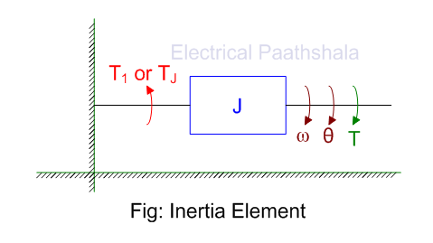
As the other two elements (torsional damper and torsional spring element) are assumed to be negligible here therefore the resisting torque T1 is equal and opposite to the externally applied torque T.
The resisting torque T1 is proportional to the angular acceleration α.
$$T_1\;or\;T_J\propto\alpha$$
$$T_1=J\alpha=T$$
$$or\;T_1=J\frac{d\omega}{dt}=T\;\;\;\;\;\left(in\;terms\;of\;angular\;velocity\right)$$
$$or\;T_1=J\frac{d^2\theta}{dt^2}=T\;\;\;\;\;\left(in\;terms\;of\;angular\;displacement\right)$$
Torsional Damper Element [Friction]
When an external torque T is applied on a body placed on a surface or inside a fluid then due to the friction present between the surface and the body or due to the viscous friction present between the fluid and the body, a resisting torque is produced which opposes the applied torque.
A torsional damper element is used to represent the friction as shown in the figure given below.
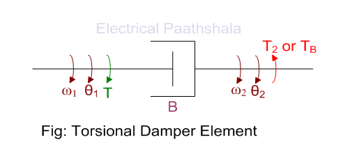
As the inertia and torsional spring elements are assumed to be negligible here therefore the resisting torque due to friction (T2 or TB) is equal and opposite to the externally applied torque T.
The resisting torque due to torsional damper element is proportional to angular velocity.
$$T_2\;or\;T_B\propto\omega$$
$$or\;T_2=B\omega=B\left(\omega_1-\omega_2\right)=T$$
$$\left(∵\omega=\omega_1-\omega_2\right)$$
$$or\;T_2=B\frac{d\theta}{dt}=B\frac d{dt}\left(\theta_1-\theta_2\right)=T$$
$$\left(∵\theta=\theta_1-\theta_2\right)$$
Here, B = Torsional Damping Constant or Torsional Friction Constant
Torsional Spring Element [Stiffness]
As we know that all the object has some order of stiffness. So, when an external torque T is applied on a body having some stiffness then due to the stiffness of that body, there will be a resisting torque (T3 or TK) which will act in the opposite direction of the externally applied torque T to resist the deformation of the body.
Torsional spring element is used to show the stiffness of the body which is shown in the figure given below:

As the inertia and torsional damper elements are assumed to be negligible here therefore the resisting torque due to torsional spring element (T3 or TK) is equal and opposite to the externally applied torque T.
The resisting torque due to torsional spring element is directly proportional to angular displacement (θ).
$$T_3\;or\;T_K\propto\theta$$
$$or\;T_3=K\theta=T$$
$$or\;T_3=K\int\omega\cdot dt=T$$
Here, K = Torsional Spring Constant (or) Torsional Stiffness Constant [N-m/rad]
Mathematical Modelling of Mechanical Rotational System
Suppose, there is a body having moment of inertia J which is placed on a surface and there is some friction between the body and the surface which is represented by torsional damping constant B and the stiffness of the body is represented by the torsional spring constant K as shown in the figure given below.

Now, when an external torque T is applied on the body then it will produce angular acceleration α. There will be three resisting torques due to the inertia of the body, friction and stiffness of the body which are T1, T2 and T3 respectively. These resisting torques will act in the opposite direction of the applied torque.
External Torque = T
As all three (Inertia, Torsional Damper and Torsional Spring) elements are present therefore we must write resisting torques due to all three elements.
Resisting Torques:
(i) Torque due to Inertia Element
$$T_1=J\alpha=J\frac{d\omega}{dt}=\frac{d^2\theta}{dt^2}$$
(ii) Torque due to Torsional Damper Element (Friction)
$$T_2=B\omega=B\frac{d\theta}{dt}$$
(iii) Torque due to Torsional Spring Element (Stiffness)
$$T_3=K\theta=K\int\omega\cdot dt$$
Now, according to d’Alembert’s principle
$$T_{ext}+T_{res}=0$$
$$T+\left[-T_1-T_2-T_3\right]=0$$
As the resisting torques acts in the opposite direction of the externally applied torque, therefore (-)ive sign is taken.
$$T=T_1+T_2+T_3$$
$$T=J\frac{d\omega}{dt}+B\omega+K\int\omega\cdot dt\;\;\;\;\;\left(in\;terms\;of\;angular\;velocity\right)$$
$$T=J\frac{d^2\theta}{dt^2}+B\frac{d\theta}{dt}+K\theta\;\;\;\;\;\left(in\;terms\;of\;angular\;displacement\right)$$
The above two equations are the mathematical model for mechanical rotational system in terms of angular velocity and angular displacement respectively.
In our next blog, we will talk about Analogous Systems, establish analogous term between mechanical and electrical system and we will also learn, how to write Force-Voltage Analogy and Force-Current Analogy.
Read More:
Introduction to control system