
In circuit analysis, we have different methods and theorems available for the analysis of various types of Circuits. Thevenin’s Theorem is one of them, which is utilized to solve certain types of complex Linear circuits.
In this blog post, we will learn What is Thevenin’s Theorem? and what are the Advantages and Limitations of Thevenin’s Theorem. How to solve Complex Linear circuits using the Thevenin Theorem?
What is Thevenin’s Theorem?
Thevenin’s Theorem states that ” Any linear electrical circuit can be replaced by an Equivalent circuit consisting of single Independent Voltage source (VTH ) and a Series Resistance ( RTH)”.
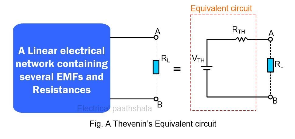
It is necessary to understand that this theorem only deals with Linear circuits. Linear circuits consist of Linear elements such as Resistor, Inductor and Capacitor. If any Non-Linear element (Diode, Transistor, etc.) is present in the circuit, then you can’t apply this theorem to solve that Circuit.
Importance of Thevenin’s theorem
In power systems, The load resistance gets changed very commonly as the multiple loads are switched on and off as per the need. Now, It is not a feasible task to perform the Nodal and mesh analysis to solve the entire circuit again and again every time when load resistance gets changed. Instead of Doing a repetitive task, we use Thevenin’s theorem. Let’s Understand with the example.
Method to solve the linear circuits with Thevenin’s Theorem
- Remove The Load Resistance from the circuit
- Calculate the Open circuit Voltage. It is called Thevenin’s Voltage (VTH ).
- Make the Voltage source as a short circuit and the Current source as an Open circuit.
- Calculate the Total Open circuit resistance. It is the Thevenin’s Resistance ( RTH).
- Draw the Equivalent circuit by connecting the Thevenin’s Voltage (VTH ) and Thevenin’s Resistance( RTH) in series.
- Connect the Load Resistance across the Two terminals of this Equivalent circuit.
- Calculate the Current through the Load Resistance and Power delivered to the load.
Let’s Understand the whole procedure with the help of an Example.
Let’s solve the Given Circuit with the help of Thevenin’s theorem, and we will calculate the Current (IL) through load Resistance (RL).
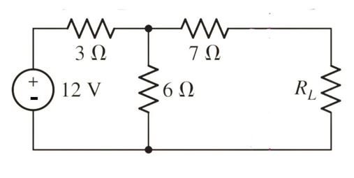
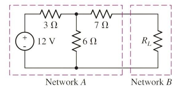
Here, In the Given Circuit, we have three resistors, one DC voltage source and one Load Resistance. Now, Consider two networks: Network A and Network B.
Network A consists of a 12 V DC source and three resistors (3Ω, 7Ω and). Network B consists of the Load Resistance only.
Step 1: Remove the Network B or simply Remove the Load Resistance (RL) and Make it a Two-terminal Open circuit.
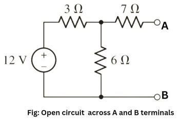
Step 2: Calculate Open circuit Voltage across A and B terminals.
To calculate the voltage across A and B terminals, we have to calculate the Voltage drop across a 6Ω Resistor. It means that we have to calculate the current flowing through the 6Ω Resistor.
As the 7Ω resistor is a part of an open circuit, So current will not flow through it. Hence, the 3Ω and 6Ω resistors are now connected in series. Total resistance would become 9Ω.
Total Current flowing in the circuit = Total Voltage / Total resistance.
I = 12V / 9Ω
I = 4/3 A
The voltage drop across 6Ω resistor = Current x Resistance
So, V6Ω = 4/3 Amp. x 6Ω
V6Ω = 8V
This is also our Open circuit voltage or Thevenin’s Voltage (VTH).
Step 3: Make the Current source (If any) an open circuit and the Voltage source a short circuit. By doing this, We can calculate the total circuit resistance ( RTH).
In the Given Example, We do not have any current source, So make the voltage source a short circuit, as shown below.
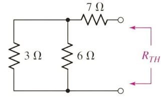
Step 4: Calculate Thevenin’s Resistance.
As we can clearly see, 3Ω and 6Ω resistors are connected in parallel, so their equivalent resistance can be easily calculated as,
Req. = 3Ω x 6Ω / 3Ω + 6Ω
Req. = 2Ω
The 7Ω resistor is connected in series with the 2Ω (Req.). Their total resistance would easily become,
RTH = 2Ω + 7Ω
RTH = 9Ω
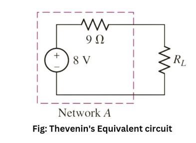
Step 5: Draw the Thevenin’s Equivalent circuit by connecting the Thevenin’s Voltage Source and Thevenin’s resistance in series.
Step 6 : Connect the Load Resistance (RL) or we can say that connect the Network B which we have removed in Step 1.
Step 7 : Calculate the Load current (IL) through Load Resistance (RL). We can also calculate the Power delivered to the Load.
Let’s consider the value of RL as 7Ω.
Total resistance in the circuit would become 16Ω (9Ω + 7Ω).
Current flowing through the circuit = 8 V / 16Ω = 0.5A
As Both resistances are connected in series, so current will be the same.
Hence, IL = 0.5 A
Power Delivered to the Load = I2R
PL = (0.5)² x 7Ω = 1.75W
If you see the Thevenin’s Equivalent circuit, then you will find that, even if the value of load Resistance gets changed, then also It will not affect the other Internal parameters of Network A. Thevenin’s Voltage and Resistance will still remain the same.
Advantages of Thevenin’s Theorem
• Complex Linear circuits can be easily transformed into Simple Equivalent circuits.
• The Internal parameters of the original circuit do not get changed when the Equivalent circuit deals with the external world.
• It is easy to calculate the new Load current and power delivered to the load when the value of the Load resistance gets changed.
Limitations of Thevenin’s Theorem
Although there are many advantages of Thevenin’s theorem, there are a few limitations also, as mentioned below,
• It deals only with the Linear circuits.
• It is applicable for two terminal circuits only.
• If the circuit doesn’t contain any source, then Thevenin’s equivalent can not be determined.
Frequently Asked Questions – FAQs
Q1. What is Thevenin’s theorem statement?
It states that “Any complex Linear circuit can be replaced with an equivalent circuit in which a single Voltage source and It’s Internal Resistance are connected in series”.
Q2. What is Thevenin’s Voltage and Thevenin’s Resistance?
Thevenin’s Voltage (VTH ) is the Open circuit Voltage across the Two terminals, and Thevenin’s Resistance is the Total resistance of the open circuit calculated by replacing the emf source with a short circuit and the current source with an open circuit.
Q3. What is the Thevenin’s Theorem Formula?
The formula to calculate the Load current in Thevenin’s equivalent circuit is,
IL = (VTH / RTH + RL)
Q4. Is Thevenin’s theorem applicable to AC circuits also?
Yes, It is applicable to AC circuits also, but keep in mind that Thevenin’s Voltage in AC circuits is expressed in Complex numbers (Polar form) whereas Thevenin’s Resistance is expressed in Rectangular form.
Read More content here,
What is Transformer oil and It’s uses, types and properties
What is the purpose of ground wires in overhead transmission system?