
In this blog we will understand the concept of Active, Reactive and Apparent Power. We will also study about Instantaneous Power. We will also see how Active, Reactive and Apparent Power are related to each other which is explained by the Power Triangle. So, at the end of this blog we will study about the Power Triangle. Hence, there is a lot of things to cover in this blog. So, let’s start.
As an electrical engineer, it is very important to have the knowledge of Active, Reactive and Apparent Power because this topic is one of the building blocks of the Power System.
Active, Reactive and Apparent Power comes into the picture in the case of AC circuits only, not in case of DC circuits because we all know that voltage and current waveforms are sinusoidal in case of AC circuits.
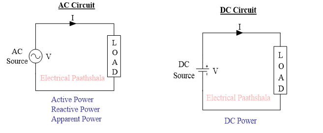
That’s why we study about Active, Reactive and Apparent Power in AC circuits only not in DC circuits. In DC circuits we study about DC power.
Before studying about Active, Reactive and Apparent Power we should know “what is instantaneous power?”
INSTANTANEOUS POWER
The power which is measured at a particular instant of time is known as Instantaneous Power.
(OR)
The multiplication of voltage and current at a particular instant of time is known as Instantaneous Power.
To understand the concept of Instantaneous power, let’s observe the waveform of some circuit shown in the diagram below.
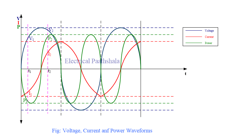
At instant t1
P1 = V1 (+ve) * I1(-ve) = -ve
Instantaneous power P1 at instant t1 is negative.
At instant t2
P2 = V2 (+ve) * I2(+ve) = +ve
Instantaneous power P2 at instant t2 is positive.
From the above example we can say that
- Instantaneous Power can be positive and negative at times.
What is Positive Power and Negative Power?
Positive Power
When power flows from the source to load in the circuit then power is called as Positive Power.

Negative Power
In some situations, power can flow from load to the source. In this case power is known as Negative Power.
- Negative power is induced in the circuit in the case of inductive load, capacitive load and in the presence of some non-linear devices like rectifier bridge.

ACTIVE POWER
To understand the concept of Active Power let’s take the example of a purely resistive circuit.
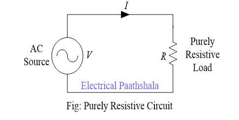
In the circuit diagram a purely resistive load is being supplied by an AC source having voltage V and the current in the circuit is I.
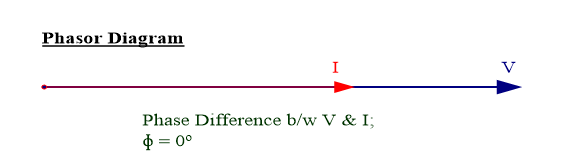
In case of a purely resistive load, both voltage and current remain in same phase as shown in the phasor diagram. It means that both voltage and current waveforms will reach their positive and negative peak at the same time and both the waveforms will cross the zero value at the same instant of time and this can be verified in the waveforms given below.
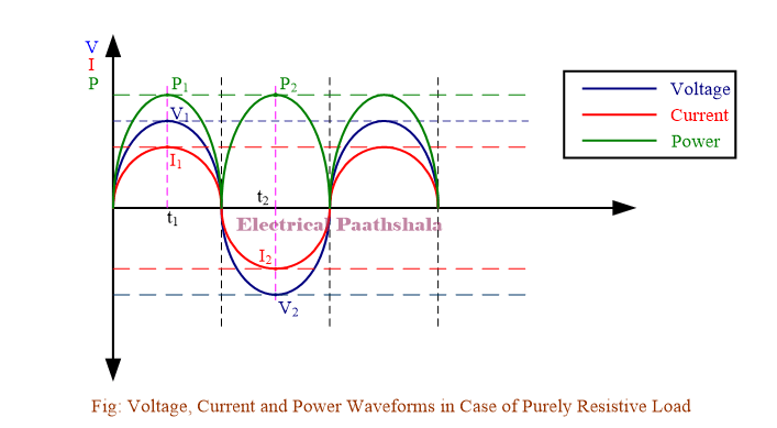
Now, we will see the polarity of instantaneous power at different instant of times.
At instant t1
P1 = V1 (+ve) * I1(+ve) = +ve
At instant t2
P2 = V2 (-ve) * I2(-ve) = +ve
Hence, in case of purely resistive load power is always positive at each and every instant of time which means that power is always flowing from the source to load. This type of power is known as Active Power.
Properties of Active Power
- Active power is always positive.
- Active power does not change its direction as you can see in the waveform.
- It always flows from source to load.
- Active power is always responsible for useful work for example: light, sound, motion, etc.
- It is represented by letter “P” and is measured in “Watts”.
- Active power is given by relation
- \(P=VI\cos { \phi }\) ; where \(\phi =Phase\quad difference\quad between\quad V\quad and\quad I\)
- In case of purely resistive load
- \(\phi ={ 0 }^{ \circ }\)
- \(P=VI\cos { { 0 }^{ \circ } }\)
- \(\Rightarrow P=VI\quad Watts\)
REACTIVE POWER
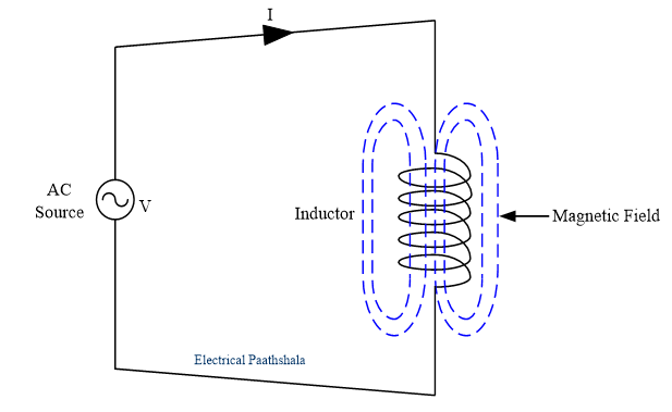
We will understand the concept of Reactive Power with the help of a purely inductive circuit.
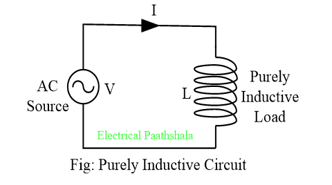
In the circuit diagram a purely inductive load is being supplied by an AC source having voltage V and the current in the circuit is I.
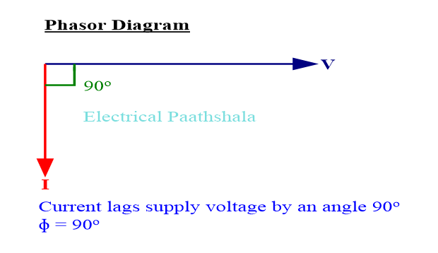
In case of a purely inductive load, current lags the supply voltage by 90o as shown in the phasor diagram.
It means that the current waveform reaches its positive peak, negative peak and crosses zero value 90o after the voltage waveform. The voltage, current and power waveforms for a purely inductive load is given below.
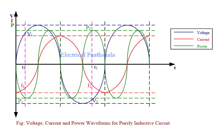
Now, we will see the polarity of instantaneous power at different instant of times.
At instant t1
P1 = V1 (+ve) * I1(-ve) = -ve
At instant t2
P2 = V2 (-ve) * I2(-ve) = +ve
Hence, in case of purely inductive load power is positive and negative as well. It means that power is going forward and coming backward between source and load exactly like a pendulum without doing any useful work in the system. This type of power is known as Reactive Power.
Now, let’s see what happens in the case of a purely capacitive load.
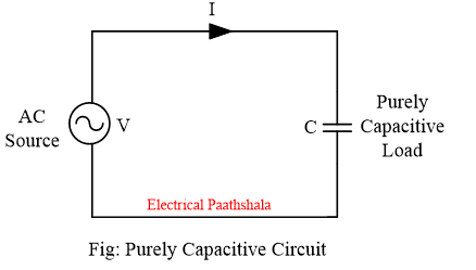
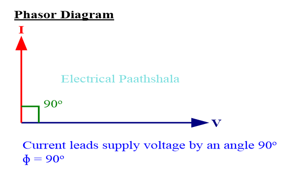
In case of a purely capacitive load, current leads the voltage by 90o which means that current waveform will reach its positive peak, negative peak and zero value 90o before the voltage waveform. The phasor diagram and waveforms for a purely capacitive load is given below.
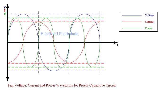
You can see in the power waveform that power is positive and negative as well which means that power is oscillating between source and load without doing any useful work. This type of power is known as Reactive Power.
If we closely observe the power waveforms in case of both purely inductive load and purely capacitive load, we will find that the magnitude of positive and negative power is exactly same.
Therefore, the average power in case of purely inductive load and purely capacitive load, is zero.
Why Power Flows Back & Forth in Case of Inductive and Capacitive Loads?
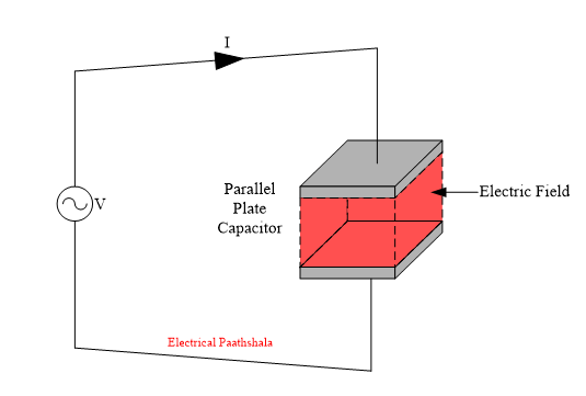
During the positive half cycle when power is positive i.e. power is flowing from source to load, the capacitor stores the energy in the form of electric field.
During the negative half cycle, the electric field of the capacitor collapses and whatever energy stored in the capacitor is sent back to the source and power starts flowing from load to source. Hence, we get negative power.
Similarly, in case of inductive load, during the positive half cycle when power is positive i.e. power is flowing from source to load, the inductor stores the energy in the form of magnetic field.
During the negative half cycle, the magnetic field of the inductor collapses and whatever energy stored in the inductor is released and sent back to the source and power starts flowing from load to source. Hence, we get negative power.
In this way, power flows back and forth in case of inductive and capacitive load.
Properties of Reactive Power
- Reactive power is positive as well as negative.
- It oscillates between source and load without contributing to any useful work.
- Reactive power is denoted by letter “Q” and is measured in “VARs” (Volt-Ampere Reactive).
- It is induced in the circuit by inductive load, capacitive load and in presence of non-linear devices.
- Reactive power is given by expression
- \(Q=VI\sin { \phi }\) ; where \(\phi =Phase\quad difference\quad between\quad V\quad and\quad I\)
- In case of purely inductive and capacitive load
- \(\phi ={ 90 }^{ \circ }\)
- \(Q=VI\sin { { 90 }^{ \circ } }\)
- \(\Rightarrow Q=VI\quad VAR\)
APPARENT POWER
The cases which we have seen until now (purely resistive, purely inductive & purely capacitive load) are standard cases.
In reality, most of the loads that we use in our daily life (For example: Electric fan, Electric iron, Induction motor etc.) are the combination of resistive & inductive load. Some loads might also be combination of resistive & capacitive load but most of the domestic and industrial loads are the mixture of resistive & inductive load.
The general circuit for a mixture of resistive & inductive load is shown in the diagram.
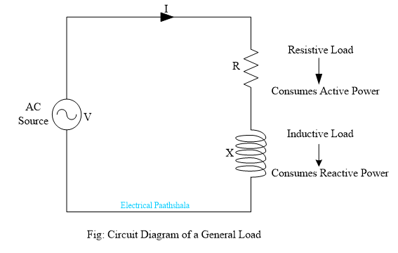
The resistive component consumes active power and the inductive component consumes reactive power. Therefore, the total power delivered by the source is the combination of active & reactive power and this power is known as Apparent Power.
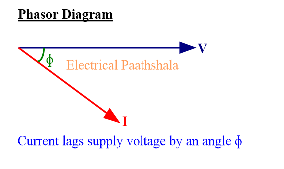
In case of combination of resistive & inductive load, current lags the supply voltage by an angle \(\phi\) which means that current waveform will reach its positive peak, negative peak and zero value with a phase delay of \(\phi\) from the voltage waveform.
The phasor diagram and waveforms for mixture of resistive & inductive load is given below.
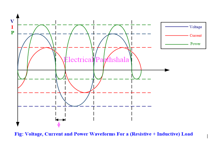
In the waveform diagram we can see that power is positive and negative as well due to the presence of active and reactive power in the circuit. Also, the magnitude of positive power is greater than magnitude of negative power.
Therefore, the average power in this case will not be zero and hence we will get some power out of the system. But in this case, average power is less as compared to the average power of purely resistive circuit.
Properties of Apparent Power
- Apparent power is the combination of active power and reactive power.
- It is denoted by letter “S”.
- Apparent power is measured in “Volt-Ampere”.
- Apparent power is given by relation
- \(S=VI\)
- If value of active power (P) and reactive power (Q) is known then apparent power can be calculated by following relation
- \({ S }^{ 2 }={ P }^{ 2 }+{ Q }^{ 2 }\)
POWER TRIANGLE
Power triangle is a right-angle triangle which shows the relationship among Active, Reactive and Apparent Power.
The base, normal and hypotenuse of the right-angle triangle represents active, reactive and apparent power respectively.
To obtain Power Triangle, we will use the phasor diagram of mixture of resistive and capacitive load.
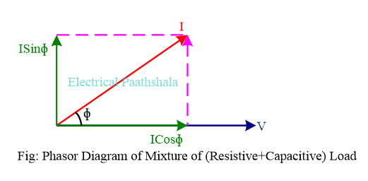
In case of mixture of resistive and capacitive load, current leads the supply voltage by some angle \(\phi\) . Now, the current can be resolved into two perpendicular components which are
- \(I\cos { \phi }\) = Component of current (I) which is in phase with the supply voltage (V).
- \(I\cos { \phi }\) is known as Active or Wattful component of current (I)
- \(I\sin { \phi }\)= Component of current (I) which is 90o out of phase with the supply voltage (V).
- \(I\sin { \phi }\) is known as Reactive or Wattless component of current (I)
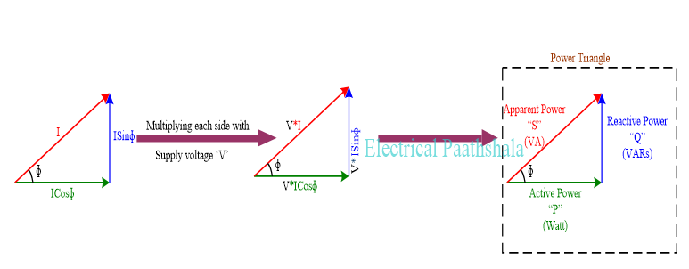
Now, to obtain Power Triangle, let’s draw the current triangle separately.
Power triangle can also be obtained by using Impedance triangle as shown in the figure below.
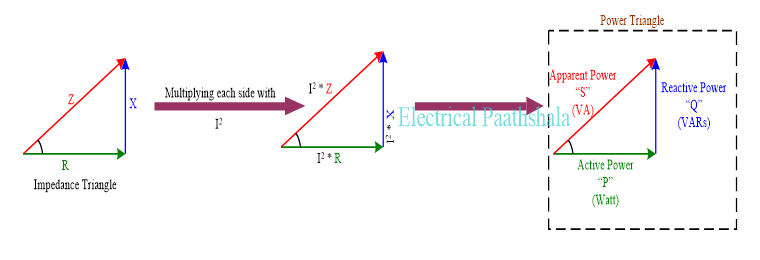
From power triangle, we can write that
\({ \left( Apparent\quad Power \right) }^{ 2 }={ \left( Active\quad Power \right) }^{ 2 }+{ \left( Reactive\quad Power \right) }^{ 2 }\)(OR)
\({ S }^{ 2 }={ P }^{ 2 }+{ Q }^{ 2 }\)
Watch active, reactive and apparent power
Read More
If I could rate it I will give a solid 10/10 , very easy explanation covered all topics solved all the doubts , thank you ❤️
Thank You Anuj for such a valuable feedback. Have a great day 🤞.