
As we have already discussed about working principle of a single phase transformer in the previous section. We discussed that whenever a conductor is placed in a changing magnetic field then according to faraday’s law, an emf will induced in it, and the transformer is also based on this principle. Now in this post we will discuss that what is the value of that induced emf and on what factors it depends. So we will derive emf equation of a single phase transformer
Primary side of a transformer is connected with an alternating source, hence the current flowing in the primary coil is sinusoidal. The flux generated by this current is also sinusoidal and we can write it as,

According to faraday’s law the induced emf can be written as

As we can write cosωt as sin(![]() – ωt) but as we can see there is negative sign in the above equation it will be modified like this
– ωt) but as we can see there is negative sign in the above equation it will be modified like this

Equation (2) may be written as

Where![]() it is the maximum value of induced emf.
it is the maximum value of induced emf.
For a sine wave, the r.m.s value of the e.m.f. is given by
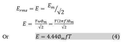
Equation (1.2.4) is called the e.m.f. equation of a transformer.
The value of induced emf depends upon flux, number of turns and frequency.
Now if someone want to write the emf equation for primary and secondary sides then simply put subscripts 1 and 2 as shown below
The primary r.m.s. voltage is

The secondary r.m.s. voltage is

Where is the maximum value of flux in webers (Wb), f is the frequency in hertz (Hz) and E1 and E2 are in volts.
The winding with higher number of turns will have a high voltage and is called the high-voltage (hv) winding. The winding with the lower number of turns is called the low-voltage (lv) winding.
Also, from Eq. (4),

It is to be noted that the induced voltage per unit frequency is constant but not same on both primary and secondary side for a given transformer.
1.3 VOLTAGE RATIO AND TURNS RATIO
The ratio E/T is called voltage per turn.
From Eq. (5), primary volt per turn

From Eq. (6), secondary volts per turn

Equations (7) and (8) shows that the voltage per turn in both the windings is same. That is,

The ratio T1/T2 is called turn ratio.
The ratio of primary to secondary turns (T1/T2) which equals to the ratio of primary to secondary induced voltages (E1/E2), indicates how much the primary voltage is lowered or raised. The turn ratio or voltage ratio is called the Transformation ratio and is denoted by the symbol a. Thus

In a practical voltage transformer, there is a very small difference between the terminal voltage and the induced voltage. Therefore, we can assume that E1 = V1, and E2 = V2. Eq. (11) is modified as

If a voltage ratio or turn ratio is specified, this is always put in the order input: output, which is primary : secondary. It is to be noted from Eq. (12) that almost any desired voltage ratio can be obtained by adjusting the number of turns.
This is all about the emf equation of a single-phase transformer, further we will discuss about step up and step down transformers and also ideal and practical transformers with their respective phasor diagrams in detail.
If you have any problem in understanding this post then please go to my YouTube channel you will find an easy explanation of this section in Hindi.