
In this blog we will study about “What is Power Factor” and the significance of power factor with a simple analogy. We will also see what are the disadvantages of low power factor. Later in this blog we will study about the types of power factor. There are a lot of things to cover in this blog. So, let’s start.
The electrical energy is almost exclusively generated, transmitted and distributed in the form of alternating current. Therefore, the question of power factor immediately comes into picture.
Power factor is one of the building blocks of the power system and that’s why it is very important to understand the concept of power factor.
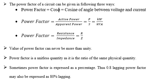
Whenever you ask someone “What is Power Factor?”, most of the students will tell you that the cosine of angle between voltage and current is called as power factor which is absolutely correct but this is not the general definition of power factor. We will talk about the general definition later in the blog but let’s first look into this statement.
POWER FACTOR
The cosine of angle between voltage and current in an AC circuit is known as Power Factor.
In an AC circuit, there is generally a phase difference ɸ between voltage and current due to the reactive component (inductance or capacitance) of the load. The term Cosɸ is called the power factor of the circuit.
If the circuit is inductive, the current lags behind the voltage by some angle ɸ. In this case power factor is referred as Lagging Power Factor.

If the circuit is capacitive, the current leads the voltage by some angle ɸ and in this case power factor is known as Leading Power Factor.

The analysis of power factor can also be done in terms of power drawn by an AC circuit. Therefore, before studying about the power factor we should have the knowledge of different types of power in an AC circuit which are “Active, Reactive and Apparent Power” and how these powers are related to each other.
There are two components of power in an AC circuit which are:
ACTIVE POWER
The power which is being utilize to do some useful work (or) the power which is used to run all the electric appliances (domestic and industrial) is known as Active Power.
- Active Power is also called as True Power / Useful Power / Actual Power / Wattful Power (or) Real Power.
- Active Power is measured in Watts (or) Kilowatts (kW).
REACTIVE POWER
The power that is being utilize by the reactive component of the load is known as Reactive Power.
- Reactive Power is neither consumed in the circuit nor it does any useful work. It merely flows back and forth between load and source.
- Reactive power is measured in Volt-Ampere Reactive (VAR).
- Reactive power is also referred as Wattless Power (or) Useless Power.
- A wattmeter does not measure reactive power.
- Reactive Power is not entirely useless though because we actually need some reactive power to create and maintain the magnetic field which rotates the motor.
- We say that reactive power is useless in the sense that we do not get any useful work from it but still, we have to pay for it. Although we do need some amount of reactive power to be able to do the work in the first place.
APPARENT POWER
The vector sum of active and reactive power is known as Apparent Power.
The unit of apparent power is Volt-Ampere (VA) or kVA.
The relationship among active, reactive and apparent power can be shown by using Power Triangle.

To obtain power triangle, let’s take the phasor diagram of a capacitive circuit as shown in the figure below.

Consider a capacitive circuit taking a leading current I from supply voltage V. Suppose that current leads the voltage by an angle ɸ.
The circuit current can be resolved into two perpendicular components, namely:
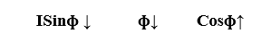
- ICosɸ Component of current (I) which is in phase with the supply voltage (V).
ICosɸ is known as Active or Wattful component of current.
- ISinɸ = Component of current (I) which is 90o out of phase with the supply voltage (V).
ISinɸ is known as Reactive or Wattless component of current.
The reactive component ISinɸ is the measure of power factor. If the reactive component is small, the phase angle ɸ is small and hence power factor Cosɸ will be high. Therefore, a circuit having small reactive current will have high power factor and vice-versa.
Now, separately drawing the current triangle.

From the power triangle, we can write
P = VICosɸ = Active Power (Watt or kW)
Q = VISinɸ = Reactive Power (VAR or kVAR)
S = VI = Apparent Power (VA or kVA)
As power triangle is a right-angle triangle, hence we can write
[Apparent Power]2 = [Active Power]2 + [Reactive Power]2
S2 = P2 + Q2
GENERAL DEFINITION OF POWER FACTOR
From power triangle, we can write
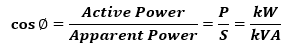
Hence, the general definition of power factor states that
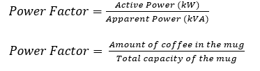
“The power factor is defined as the ratio of active power to the apparent power.”
This is a perfectly general definition of power factor and is applicable to all cases from the power factor of a single induction motor to the entire building.
The lagging *reactive power is responsible for low power factor. It is clear from the power triangle that smaller the reactive component, the higher the power factor of the circuit.
From power triangle, we can write
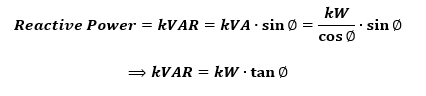
*Note: If the current lags behind the voltage, the reactive power is known as lagging reactive power. However, if the circuit current leads the voltage, the reactive power is known as leading reactive power.
Power triangle can also be obtained from Impedance Triangle as shown in the diagram below.

Conclusion:
SIGNIFICANCE OF POWER FACTOR
Power factor is a measure of how efficiently electrical power is consumed.
Power factor tells us how much value for money we are getting for the power that we consume.
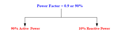
Example: Suppose power factor of your house is 0.9 lagging (or) 90% lagging. What does this suggest?
It suggests that out of 100% power that is being supplied to you by the supplier, only 90% of the power is useful power (or) active power that is being utilized to run all the appliances of your house. The remaining 10% power is reactive power that is useless for you but still you have to pay for it.
It is not the concern of the supplier that how much power is useful for you and how much is wasted. You have to pay for the entire 100% power.
Now, let’s understand it with a simple analogy.
Power Factor Analogy:
Suppose, you go to a cafe and order a mug of coffee. Now remember, you are paying for the entire mug, irrespective of the fact that the entire mug is not filled with coffee only, there is some foam also.
The more coffee you have in the mug, less foam will be there and hence you will get very good value for money. If there is a lot of foam and less coffee in the mug then in this situation, you are not getting good value for money.

In this analogy, the coffee represents Active Power (or) kW. This is the useful stuff that you want and that does the useful work.
The foam represents Reactive Power (or) kVAR. This is the useless stuff which you don’t want but there will always be some and even if you can’t use it, you have to pay for it.
The combination of these two powers i.e. the entire capacity of the coffee mug represents Apparent Power (or) kVA.
Hence, in this analogy, the power factor represents how much value for money you are getting for the coffee that you consumed.
If power factor is close to “1” then we will get maximum value for money because in that case reactive power consumption will be minimum.
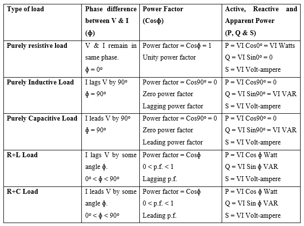
POWER FACTOR FOR DIFFERENT TYPES OF LOAD
Purely Resistive Load
Suppose an AC voltage (V) is applied across an electric load of pure resistive nature such as electric bulb or immersion rod etc. and current (I) starts flowing in the circuit as shown in the diagram below.

In case of a purely resistive load both voltage and current remains in same phase which means both voltage and current waveforms attain their respective positive, negative and zero value at the same time.
Phasor diagram and voltage & current waveforms for a purely resistive load is shown in the figure below.


In case of purely resistive load power is always positive at each and every instant of time which means that power is always flowing from the source to load. This type of power is known as Active Power.
Phase difference between voltage & current
ɸ = 0o
Power Factor = Cosɸ = Cos0o = 1
Hence in case of purely resistive load power factor is 1 which is known as unity power factor. It is the perfect value of power factor and all the time we try to make our power factor as close as possible to 1.
Unity power factor suggests that all the electricity drawn from the supply goes into doing work and in this case generating heat.
Purely Inductive Load
Suppose, a purely inductive load is being supplied by an AC source having voltage V and the current in the circuit is I as shown in the figure below.

In case of purely inductive load current lags the voltage by an angle of 90o. It means that current waveform will reach its positive peak, negative peak and zero value, 90o after the voltage waveform.
Phasor diagram and voltage & current waveforms for a purely inductive load is shown in the figure below.


In case of purely inductive load, power is positive as well as negative (as we can see in the power waveform). It means that power is going back and forth between source and load without doing any useful work. This type of power is known as Reactive Power.
Phase difference between voltage & current
ɸ = 90o
Power Factor = Cosɸ = Cos90o = 0
Hence in case of purely inductive load power factor is zero which is known as zero power factor.
Purely Capacitive Load
Suppose, a purely capacitive load is being supplied by an AC source having voltage V and the current in the circuit is I as shown in the figure below.

In case of purely capacitive load current leads the voltage by an angle of 90o. It means that current waveform will reach its positive peak, negative peak and zero value, 90o before the voltage waveform.
Phasor diagram and voltage & current waveforms for a purely capacitive load is shown in the figure below.


In case of purely capacitive load power oscillates between source and load without doing any useful work. This type of power is known as Reactive Power.
Phase difference between voltage & current
ɸ = 90o
Power Factor = Cosɸ = Cos90o = 0
Hence in case of purely capacitive load power factor is zero.
Resistive + Inductive (R+L) Load
Practically most of the electrical loads comprise of slight inductive nature due to the presence of winding or coil. Therefore, most of the loads that we use in our daily life, are the mixture of resistive and inductive loads.
Example: Electric fan, tube light with chock coil, washing machine, induction motor, etc.
The general circuit diagram of R+L load is shown in the figure below.

In case of R+L load, current lags the voltage by some angle ɸ due to the inductive nature of the load. It means that current waveform will reach its positive peak, negative peak and zero value with a phase delay of ɸ from the voltage waveform.
Phasor diagram and voltage & current waveforms for R+L load is shown in the figure below.


In case of R+L load, resistive component consumes active power and reactive component consumes reactive power. Therefore, the total power delivered by the source is the combination of active and reactive power which is known as Apparent Power.
Phase difference between voltage and current = ɸ
Power Factor = Cosɸ; 0 < Cosɸ < 1
Since, current lags the supply voltage, therefore power factor is called as lagging power factor.
Resistive + Capacitive (R+C) Load
Some of the loads are also the mixture of resistive and capacitive load. The circuit diagram of R+C load is shown in the figure below.

In case of R+C load, due to the presence of capacitance the load opposes any change in voltage and that’s why voltage lags behind current in phase by some angle ɸ.
We can also say that current leads the supply voltage by some angle ɸ.
Phasor diagram and voltage & current waveforms for R+C load is shown in the figure below.


In case of R+C load, resistive component consumes active power and reactive component consumes reactive power. Therefore, the total power delivered by the source is the combination of active and reactive power which is known as Apparent Power.
Phase difference between voltage and current = ɸ
Power Factor = Cosɸ; 0 < Cosɸ < 1
Since, current leads the supply voltage, therefore power factor is called as leading power factor.
Table: Power Factor for Different Types of Load
Disadvantages of Low Power Factor
The power factor plays an important role in AC circuit since power consumed depends upon power factor.
As we know that,
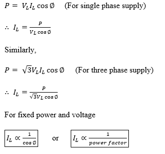
It is clear from above that for fixed power and voltage, the load current is inversely proportional to the power factor. Lower the power factor, higher is the load current and vice-versa.
A power factor less than unity results in following disadvantages:
Large kVA rating of equipment:
The electrical machinery (e.g., alternator, transformer, switchgear, etc.) is always rated in kVA.
It is clear that kVA rating of the equipment is inversely proportional to power factor. The smaller the power factor, the larger is the kVA rating. Therefore, at low power factor, the kVA rating of the equipment has to be made large, making the equipment larger and expensive.
Greater conductor size:
As we know that for fixed power and voltage, the load current is inversely proportional to the power factor. Therefore, to transmit or distribute a fixed amount of power at constant voltage, the conductor will have to carry more current at low power factor which will result in increased size of the conductor.
Large copper losses:
The large current at low power factor causes more I2R losses in all the elements of the supply system which results in poor efficiency.
Poor voltage regulation:
The large current at low lagging power factor causes greater voltage drops in alternator, transformers, transmission and distribution lines. This results in the decreased voltage available at the supply end, thus impairing the performance of utilization devices. In order to keep the receiving end voltage within permissible limits, voltage regulators are required.
Reduced handling capacity of the system:
The low lagging power factor reduces the handling capacity of all the elements of the system. It is because the reactive component of current prevents the full utilization of the installed capacity.
Types of Power Factor
Basically, there are two types of power factor which depends on the nature (linear and non-linear) of the load:
- Displacement Power Factor
- Distortion Power Factor
Displacement Power Factor
In case of linear loads, the degradation of the power factor is just because of the reactive component (inductor and capacitor) of the load. In the presence of inductive or capacitive load, a phase displacement is introduced between voltage and current due to which power factor degrades.
This type of power factor is known as Displacement power factor.
Distortion Power Factor
When non-linear loads (e.g., rectifier bridges) are present in the system then these non-linear loads introduce harmonics in the current waveform. Because of this harmonic distortion of current, power factor gets degraded.
So, in case of non-linear loads, power factor is known as Distortion Power Factor.
Now, in actual system where both linear and non-linear loads are present, the total power factor of the system is given by relation:

Watch “what is power factor?”
Read More